harnessPRO
A visual editor for designing wire harnesses from start to finish: schematic, physical layout, bill of materials, and manufacturing drawings — right in the browser, with your account saving everything so you have it on every device.
This manual documents every feature: each view, each menu, each configuration option and each part type, with examples and step-by-step instructions. Use it as a reference or follow it from beginning to end with the full tutorial.
Your account
Everything is saved to your account and follows you to any device. Offline you keep editing.
4 synchronized views
Schematic, Layout, Parts and Connections share the same model in real time.
Interoperable
Import and export JSON v0.8 compatible with harness.design.
Production drawings
PDF with title block, per-connector tables, cut list, netlist and labels.
Getting startedGetting started
The typical workflow has four phases, one per view. There is a single underlying model: changing something in one view is instantly reflected in the others.
Create or load a harness
☰ → New harness (empty) or Load demo harness (sample).Draw the schematic
In Schematic: right-click the canvas to add components, drag between pins to connect them.Lay out the harness
In Layout: position the components; the main trunk routes itself — add branch points wherever it splits.Assign parts
In Parts: create or assign part numbers; the BOM is generated automatically.Validate and export
Review Connections, resolve warnings and export the production drawing.
Getting startedThe interface
The top bar contains, from left to right:
| Element | Function |
|---|---|
| ☰ Main menu | File, library, settings and export (see below). |
| Harness name | Editable; identifies the harness and appears in exports. |
| Search box | Filters live by signal, designator or name; highlights matches and their wires, dimming the rest. |
| View selector | Schematic · Layout · Parts · Connections, color-coded by mode. |
| Split view | Opens several views at once; the selection propagates between them. |
Canvas panels
- Selection panel (top right): when a component is selected, shows its name, ID, type, number of wires, total gauge and the list of connections; lets you change the number of cavities.
- Warnings panel (top left): with "Show warnings" enabled, lists validation issues.
- Toolbar (bottom right): display toggles (see below).
Getting startedMain menu ☰
Gathers everything related to the file, organization and export.
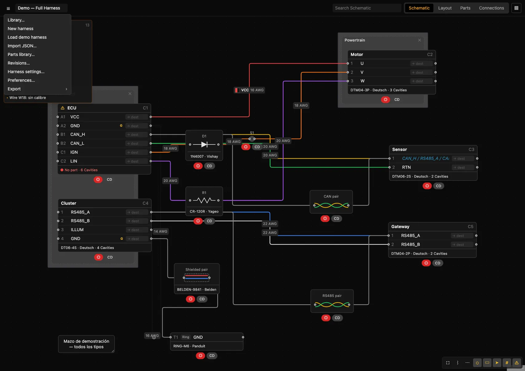
| Option | What it does |
|---|---|
| Library… | Opens the harness library (projects and documents). See Library. |
| New harness | Creates an empty harness (asks for confirmation; the current one is lost if unsaved). |
| Load demo harness | Loads the full demonstration harness. |
| Import JSON… | Opens a JSON file. Detects whether it is harness.design's v0.8 format and converts it, or loads the internal format. |
| Parts library… | Opens the shared parts library. See Parts Library. |
| Revisions… | History of harness snapshots. See Revisions. |
| Harness settings… | Harness settings: units, formboard, read-only. See Harness settings. |
| Preferences… | App settings: theme, input, performance. See Preferences. |
| Export › | Export submenu (Excel, CSV/JSON, PDF). See Export. |
Getting startedCanvas toolbar
Present in Schematic and Layout (bottom right). By default the five toggles on the right are active. Each toggle has its own keyboard shortcut.
| Icon | Name | Shortcut | What it does |
|---|---|---|---|
| ⛶ | Fit to view | F | Frames the whole design (or centers the selection). |
| ⌇ | Highlight nets | N | When selecting, highlights the entire electrical net instead of just the direct connection. |
| ┄ | Dash undefined routes | U | Draws wires with no defined route/gauge as dashed (in Layout: "Dash empty bundles"). |
| ⬡ | Show parts | P | Shows the assigned part under the footer of each component. |
| ▭ | Show coverings | C | Shows the coverings applied. |
| ➤ | Show destinations | D | Adds a destination field next to each cavity to create connections quickly. |
| # | Show component IDs | I | Shows the designator (C1, R1…) of each component. |
| ⚠ | Show warnings | W | Enables the validation warnings panel and the ⚠ badges. |
DesignSchematic view
The electrical representation of the harness: components with their pins/cavities and the wires that link them.
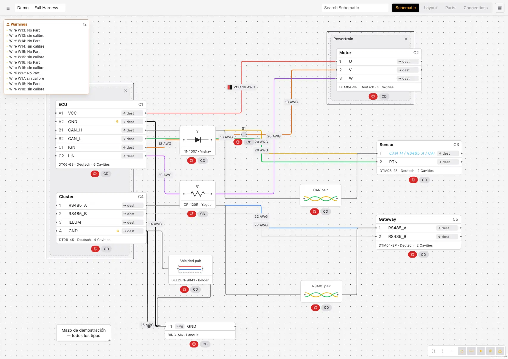
Basic operations
- Add a component: right-click the canvas → choose a type.
- Connect: drag from the connector (circle) of one pin to another.
- Move: drag the component (smooth transition).
- Select multiple: selection box or Shift+click.
- Rename a component: double-click the name in the header.
- Edit a signal: double-click the cavity name.
- Shape a wire: drag the wire itself (creates a layout point). A single click just selects it.
- Delete: select and press Delete.
Quick pills on each component
Under each component there are two shortcuts: ◎ (red) opens Assign Part, and CD adds/removes a quick covering (Braided sleeve).
SchematicCreating components
Right-clicking the canvas opens the creation menu:
The component appears at the click position with an automatic designator (C1, T1, S1, D1, R1, X1, TW1, N1). Each type is detailed in the following sections.
ComponentsConnector
A pluggable interface with cavities. It is the harness's central component. Its context menu (right-click on the node):
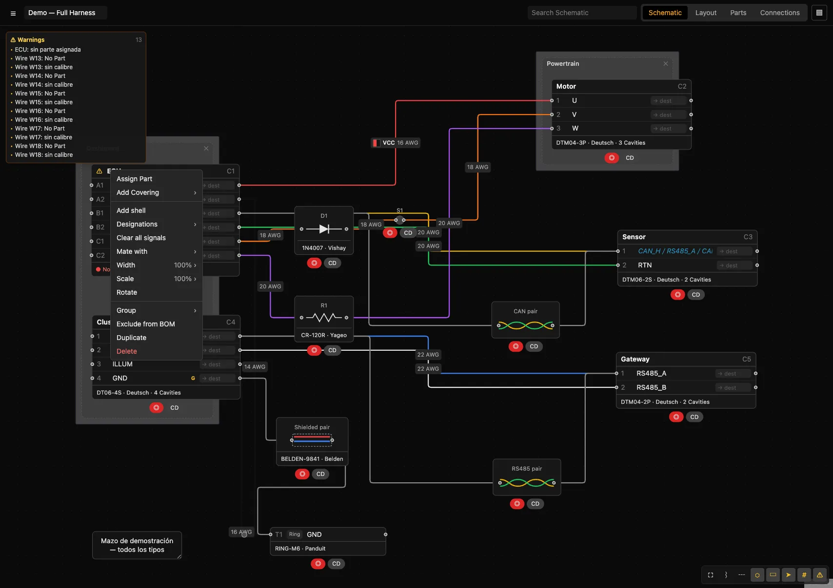
| Option | Detail |
|---|---|
| Assign Part | Opens the dialog to search for/create and assign a connector part. |
| Add Covering › | None · Braided sleeve · Convoluted loom · Tape · Heatshrink. |
| Add/Remove shell | Adds or removes the "Shell" row (lets you connect a wire directly to the housing, e.g. coax shield ground). |
| Designations › | Numbers (1,2,3) · Alphabetical (A,B,C) · Grid (A1,A2,B1 — asks for number of columns) · Custom (free label per cavity). |
| Clear all signals | Clears the signal of every cavity (they revert to "Signal"). |
| Apply configuration | (Only with a part assigned) Applies the contacts from the connector part's default configuration to the cavities. |
| Mate with › | List of connectors/terminals to mate with; below, "Unmate" for those already mated. |
| Width › | 50% · 75% · 100% · 125% · 150% (node width). |
| Scale › | 50% · 75% · 100% · 125% · 150% · 200%. |
| Rotate | Rotates 90°. |
| Group › | + New group · existing groups · Ungroup (see Group). |
| Exclude from BOM | Excludes the component from the bill of materials. |
| Duplicate | Creates a copy with a new designator. |
| Delete | Deletes the component and its connections. |
Defining cavities step by step
Set the count
Select the connector; in the selection panel type the number of cavities (or use −/+). Equivalent to the1-13range in other tools.Choose the designation
Menu → Designations → Numbers / Alphabetical / Grid / Custom.Adjust specific cavities
Right-click a cavity: Move up/down, Add cavity below, Delete cavity, Set designation (Custom). See Cavity menu.Enter the signals
Double-click each cavity to set its signal.
Mates
With Mate with you declare that two connectors are plugged together: their cavities are mapped 1:1 into the same net. Validation warns if the number of cavities doesn't match or the genders aren't opposite.
ComponentsTerminal
The individual termination of a wire. Context menu:
| Option | Detail |
|---|---|
| Type › | Pin · Socket · Ring · Spade · Fork · Bullet · Blade. |
| Mate with › | Mate with another connector/terminal. |
| Do not propagate / Propagate | Controls whether the terminal's signal extends through its net. |
| Make signal global / local | Global signal: same global signal with the same name = same net with no physical wire. |
| Assign Part · Width · Scale · Rotate | As with other components. |
ComponentsSplice · Diode · Resistor
Splice
A joint linking two or more wires. Represented as a point. Menu: Assign Part, Add Covering, Scale. Can also be created from a wire with Add splice.
Diode
Lets current flow in a single direction; diode symbol. Menu: Flip Direction (reverses anode/cathode), Assign Part, Width, Scale, Rotate.
Resistor
A resistor (zigzag symbol). Menu: Assign Part, Width, Scale, Rotate.
ComponentsCable · Twisted wires · Note
Cable
A bundle of wires (cores) under a single jacket, with optional shielding. Menu: Add shield / Remove shield (draws the braid), Assign Part, Width, Scale, Rotate. Can also be created from wires with Make cable.
Twisted wires
A twisted pair or group (CAN, RS485…), drawn as interwoven strands. Created by selecting two or more wires and using Twist together. Wires in a pair are marked with their partner in the "Twisted With" column of Connections.
Note
A free-text annotation. Menu: Align (left/center/right), Width, Scale. Double-click to write.
ComponentsGroup
Groups related connectors together (e.g. the ones going to an ECU). Appears as a rectangle with an editable name, sitting behind its members.
Create
Select several components, right-click → Group › → + New group.Add to a group
Menu → Group › → choose an existing group.Undo
Menu → Group › → Ungroup.
The "Group" column in Connections shows which group each connection belongs to (when both ends are in the same group).
SchematicCavity (pin) menu
Right-click a specific cavity on a connector:
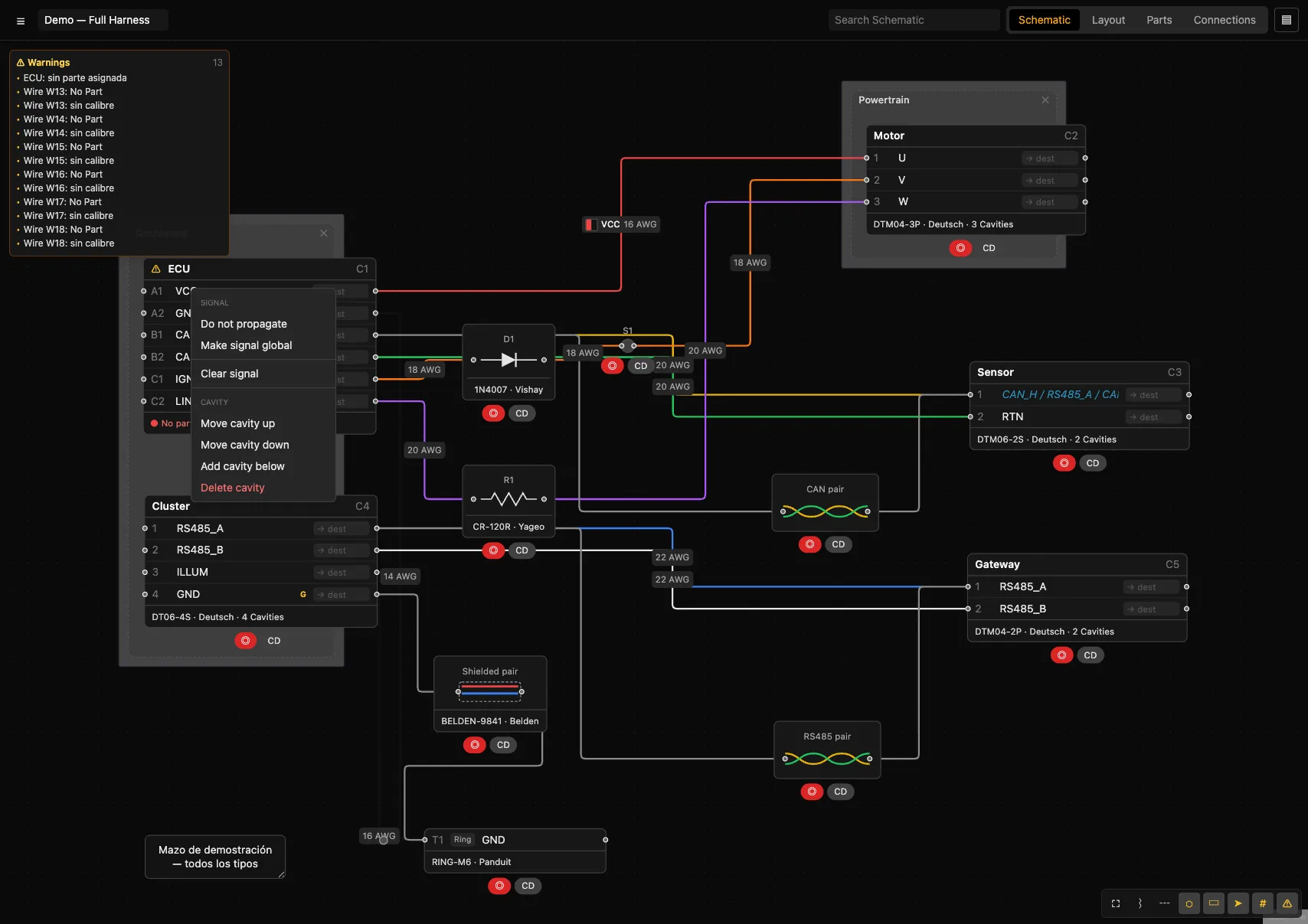
The "Cavity" section only appears on connectors. "Set designation" only appears with Custom designation.
DesignSignals and nets
A net is the set of pins connected electrically. It is calculated automatically from the wires, splices and mates.
Propagation
When you type a signal into a cavity, it propagates through its net: the empty cavities in that net show the inherited signal in italic blue. If several different signals coexist in a net, all of them are shown (conflict).
Options (right-click on the signal)
- Do not propagate — the cavity keeps its signal but does not extend it (marked
⊘). - Make signal global — two global signals with the same name = the same net with no physical wire (useful for grounds). Marked G.
Highlighting and selection
- Highlight nets (N): lights up the whole net on selection.
- Select wires on net (wire menu): selects every wire in the net, useful for assigning the same part in bulk.
DesignWires
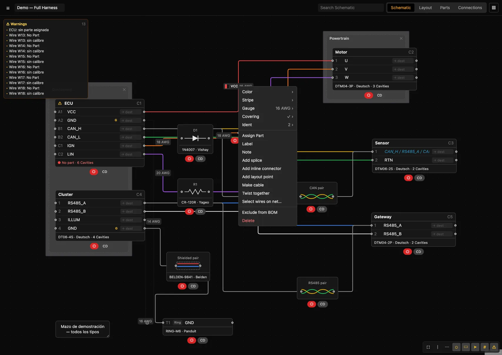
Right-clicking a wire opens its full menu:
| Option | Values / detail |
|---|---|
| Color / Stripe | Red, Black, Blue, Yellow, Green, White, Orange, Brown, Violet, Grey. Stripe accepts "None". |
| Gauge | 22 · 20 · 18 · 16 · 14 · 12 · 10 AWG. |
| Covering | None · Braided sleeve · Convoluted loom · Tape · Heatshrink. |
| Ident | Adds color bands (one per color), a text label (Label…), and "Clear idents". Drawn as stripes alongside the wire. |
| Assign Part | Assigns a wire part (part number, gauge, color). |
| Label / Note | Visible label for the segment / internal note (appears in the Notes column). |
| Add splice | Inserts a splice in the middle, splitting the wire in two. |
| Add inline connector | Inserts a 2-way connector in the middle. |
| Add layout point | Adds a shaping point at the click position (draggable). |
| Make cable | Converts the selected wires into a cable (one core per wire). |
| Twist together / Untwist | Groups the selection as a twisted pair / undoes it. |
| Select wires on net… | Selects the whole net to assign a part in bulk. |
| Exclude from BOM · Delete | Exclude from BOM · delete the wire. |
LayoutLayout view and the main trunk
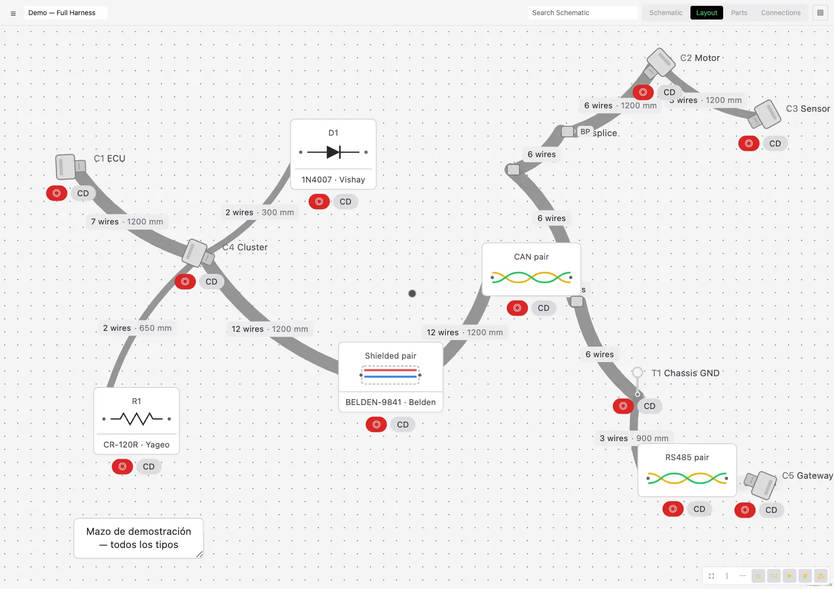
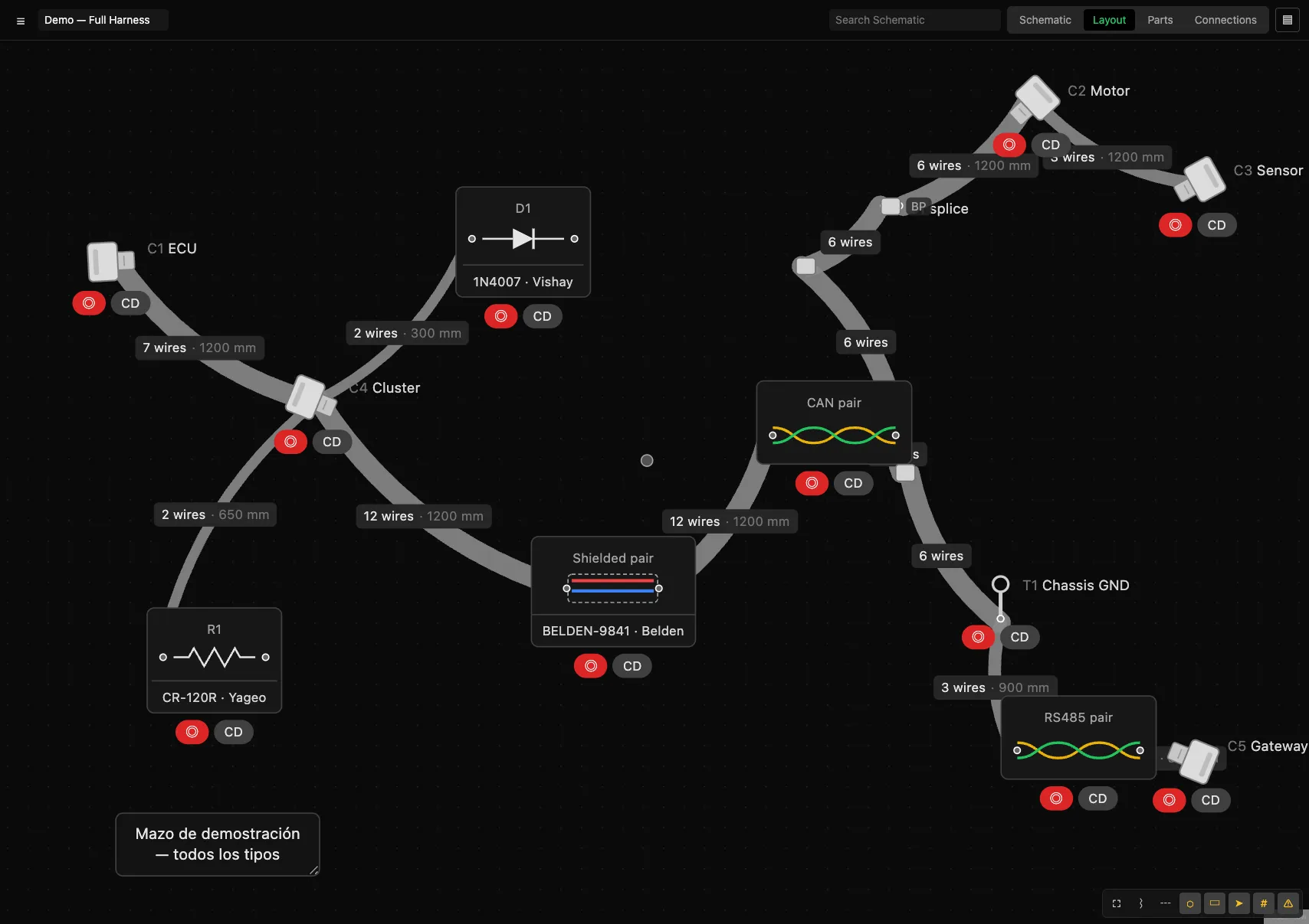
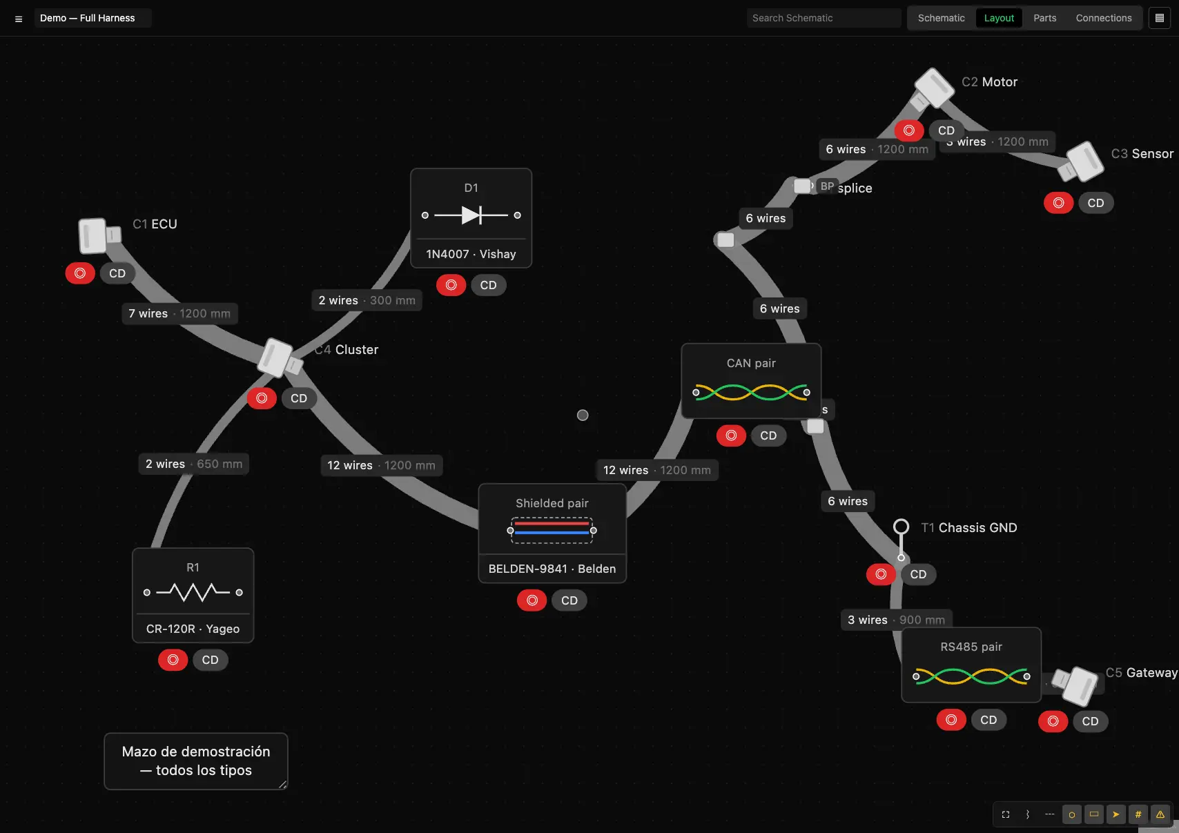
The physical arrangement: a single harness that branches, like a real motorsport harness, not a bundle of lines for every pair of connectors.
How routing works
The routing is yours: the Layout starts showing only the parts, with no lines. Trace the runs by dragging from one connector to another (or from a connector to a boot), or by selecting a component and using Unir con el mazo in another one’s context menu. Each conductor follows the traced runs between its ends and trunk segments accumulate wires: thickness is proportional to the conductor count and each run shows its length. «Quitar tramo del mazo» (run menu) undoes it.
Physical components
- Connectors: housing + backshell; the harness starts exactly at the mouth of the backshell, as in real life, and the symbol auto-orients the backshell toward the cables — toward all of them when there are several bundles. Rotate them by hand from their menu if you prefer another orientation.
- Terminals: a symbol based on their type (ring, fork…).
- Splices/diodes/resistors: a symbol, placeable along the harness.
Drag components to reposition them; their Layout positions are independent of their Schematic positions.
LayoutBranch points and boots
Add
Right-click on empty space in Layout → creates a branch point that is inserted into the nearest harness segment and diverts the trunk through it.Move
Drag it; the harness is recalculated on release.Boot / delete
Right-click the branch point → Add boot (conical sleeve) or Delete. Delete also removes it.
Bundles are routed orthogonally by default (horizontal and vertical runs with rounded corners); with layout points the routing is free. A branch point with a boot shows the moulded sleeve: one arm per mouth that carries a bundle — never extra empty arms. Pick the type (straight, elbow, Y, T, tri, quad) and rotation from the right-click menu.
LayoutBundle menu
Right-click a harness segment. Applies to every wire in the segment.
To fix the segment's length, edit the bundle's length field (also reflected in the cut list). "Make orthogonal" converts the run into a right-angle routing.
LayoutFormboard (1:1 scale)
Turns the Layout into a physically scaled board for building the harness on a template. Enabled at ☰ → Harness settings → Formboard → Use formboard for layout.
| Setting | Values |
|---|---|
| Panel size | A4 · A3 · A2 · A1 |
| Orientation | Landscape · Portrait |
| Scale | Pixels per millimeter (defines the real-scale grid) |
| Bend radius | Default bend radius for the bundles (mm) |
With the formboard enabled, the canvas shows a 10 mm scale grid, and you can export the panels as PDF (Export).
PartsParts view and BOM
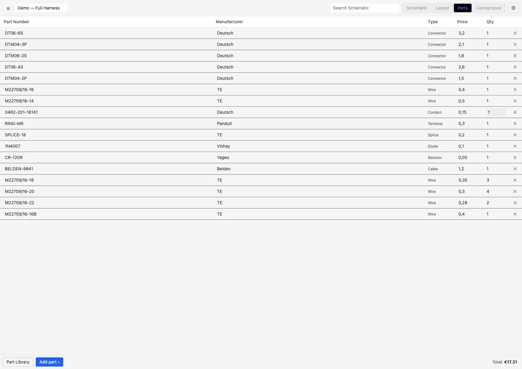
The catalog of part numbers used in the harness and the bill of materials, generated and updated automatically.
Controls
- Part Library — opens the shared parts library.
- Add part ▾ — creates a part of the chosen type (menu grouped into Basic / Accessory / Covering / Terminal).
- Columns: Part Number, Manufacturer, Type, Price, Qty. Double-click the row to open the editor.
- Qty is calculated by usage (assignments); if not assigned, it is editable.
- Total — sums price × quantity, in the harness's currency.
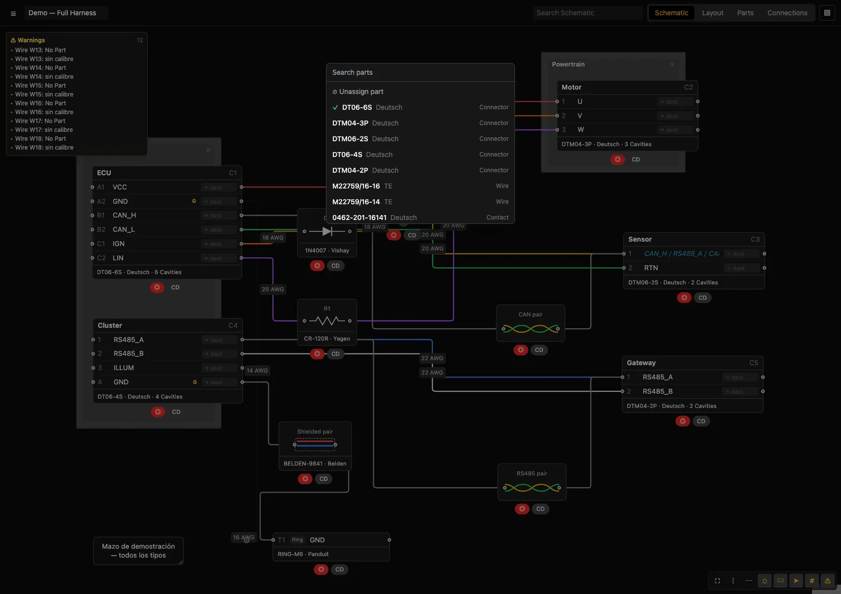
Assigning a part
From the component
Right-click → Assign Part. Search by number or manufacturer, or create a new one with "+ New part".In bulk on a net
On a wire → Select wires on net… assigns the same part to every wire in the net.
PartsPart editor
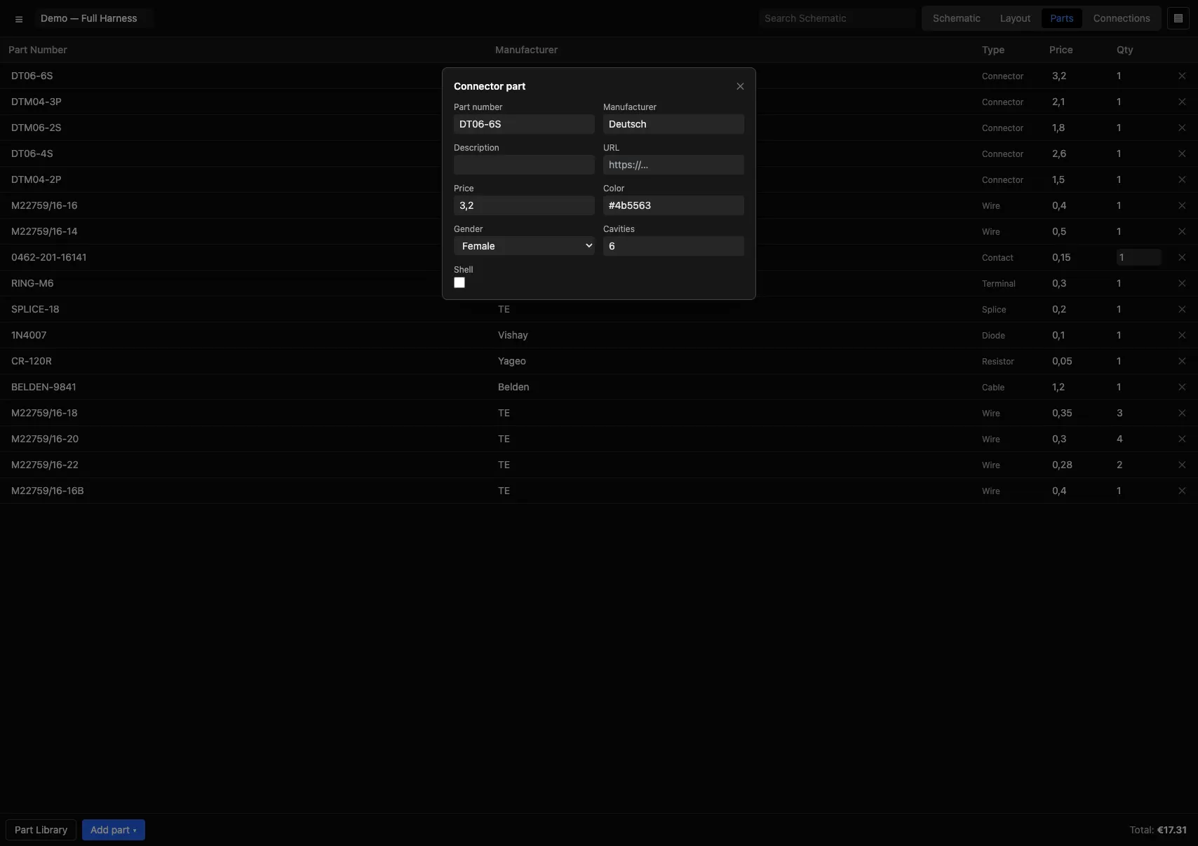
Double-clicking a part (or "Type") opens the editor. It shows the common fields plus the type-specific ones.
Common fields (all types)
Part number · Manufacturer · Description · URL · Price · Color.
PartsPart types and their fields
harnessPRO models industry-standard part types, grouped into four families. Gauges accept AWG, mm², cmil or kcmil units.
| Family | Type | Own fields |
|---|---|---|
| Basic | Wire | Gauge, Stripe color |
| Cable | Cores, Shielded, Gauge | |
| Connector | Gender (Male/Female), Cavities, Shell, Configurations | |
| Splice | Min gauge, Max gauge | |
| Diode | Voltage (V), Current (A) | |
| Resistor | Resistance (Ω), Power (W) | |
| Generic | Common fields only | |
| Accessory | Contact | Type (Crimp/Solder/Other), Gender (Pin/Socket), Min/Max gauge |
| Cavity seal | Common fields only | |
| Lock | Common fields only | |
| Dust cover | Common fields only | |
| Boot | Common fields only | |
| Backshell | Common fields only | |
| Covering | Covering | Type (Heatshrink/Corrugated tubing/Spiral wrap/Tape/Tubing/Braided sleeve/Other), Min/Max diameter, Fixed length, Length |
| Terminal | Terminal | Type (Ferrule/Ring/Spade/Male Quick Connect/Female Quick Connect/Loose), Size, Min/Max gauge |
PartsParts Library
A parts library shared across all your harnesses. From the Parts view → Part Library, or ☰ → Parts library…
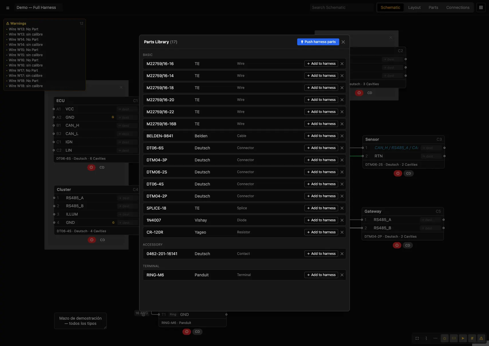
- ⬆ Push harness parts — uploads the current harness's parts to the library (identified by Part Number: creates or updates).
- + Add to harness — brings a part from the library into your design.
- Inline editing of Part Number/Manufacturer and deletion. Parts are grouped by family.
PartsConnector Configurations
A connector part can define configurations (e.g. "Sealed") with default accessories: contact, lock, dust cover, boot, backshell. When the connector is assigned to a component, Apply configuration (connector menu) applies those accessories to the cavities.
TablesConnections view
The wiring table: one wire per row. Configurable columns from the top bar.
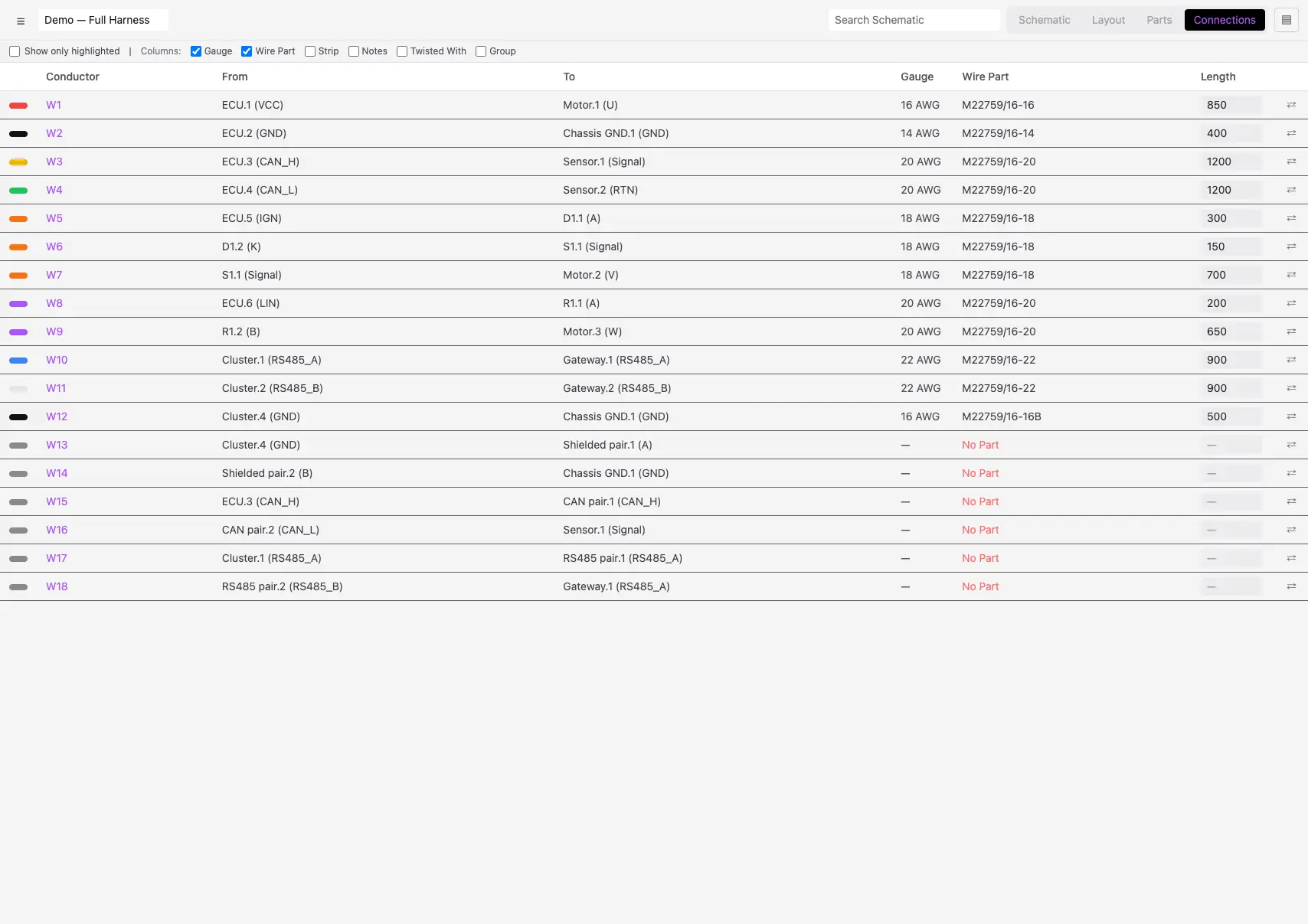
| Column / control | Content |
|---|---|
| Wire / From / To | Identifier and endpoints. |
| Gauge | Gauge in AWG. |
| Wire Part | Assigned part, or No Part. |
| Strip | Strip length (editable, for the cut list). |
| Notes | Wire note (editable). |
| Twisted With | Wires from the same twisted pair. |
| Group | Group it belongs to. |
| Length | Length (mm), editable. |
| ⇄ (swap) | Swaps From/To for the row. |
| Show only highlighted | Filters to the connections highlighted in other views. |
TablesValidation (DRC)
With Show warnings (W) enabled, harnessPRO checks the design and shows a warnings panel and a ⚠ badge on the affected components.
| Warning | When it triggers |
|---|---|
| No part (component) | Component with no part (and not excluded from BOM). |
| No Part (wire) | Wire with no wire part. |
| No gauge | Wire with no gauge. |
| Not Used | Catalog part not assigned to anything. |
| Cavities mismatch | Connector's number of cavities ≠ its connector part. |
| Mate cavities / gender | Mated connectors with a different number of cavities or the same gender. |
| Gauge vs contact | Wire gauge outside the range of the cavity's contact. |
| Gauge vs part | Wire gauge ≠ that of its wire part. |
ManagementLibrary
☰ → Library…. Organizes harnesses into projects (folders) with a thumbnail, date and name.
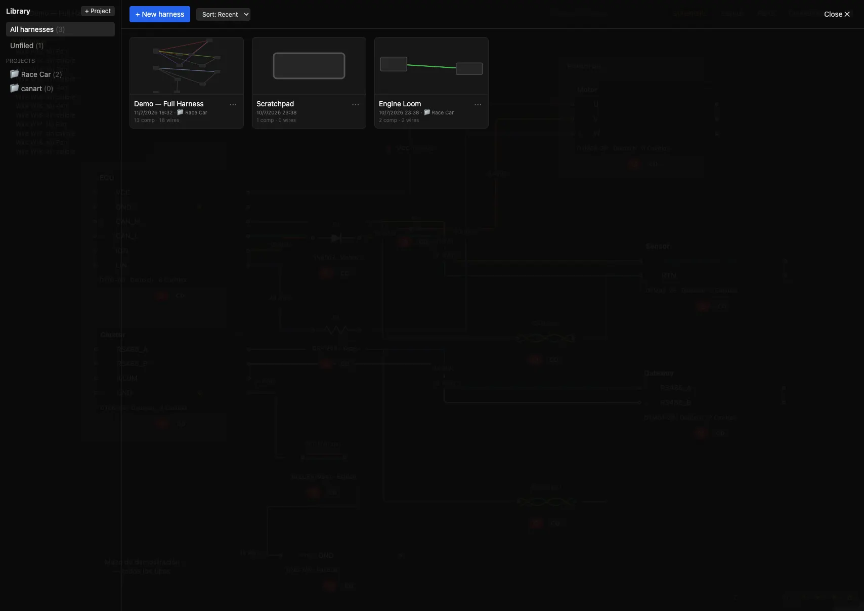
- Projects: "+ Project" creates a folder; "All harnesses" and "Unfiled" are quick views.
- Per document (⋯ menu): open, rename, duplicate, move to project, export, delete.
- The active harness is saved automatically to its document.
ManagementYour account and the cloud
harnessPRO keeps all your work in your account — harnesses, projects, parts library, revisions and preferences — not in the browser. Sign in with the same account on another computer or on your phone and you will see exactly the same.
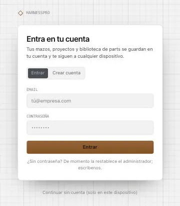
- Create account: name, email and password. If this browser already had harnesses, they are uploaded to the new account the first time you sign in: nothing is lost.
- Automatic saving: every change is sent to the server right away. The indicator ☁ saved to your account (in the library and in the editor bar) shows when it last happened; with no network it shows offline · N pending changes and uploads them by itself when the connection returns.
- Other devices: whatever you change elsewhere shows up here when you come back to the tab (and every minute). If the harness you have open changed on another device it is not overwritten: the notice newer version in your account appears with Load it or Keep mine.
- Continue without an account (link under the form): the app works with this browser only, as before. Sign in in the header takes you back to the sign-in screen.
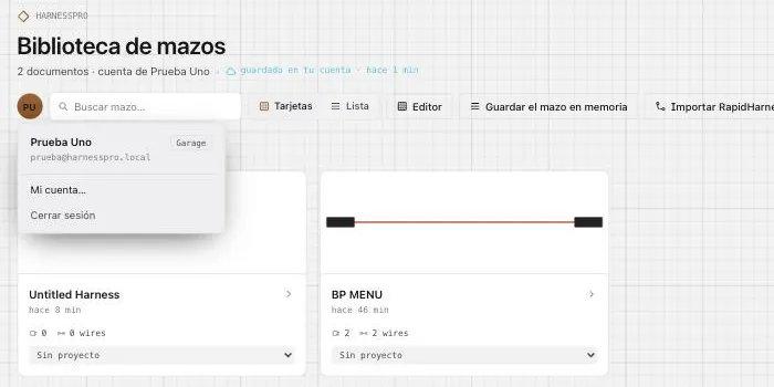
My account
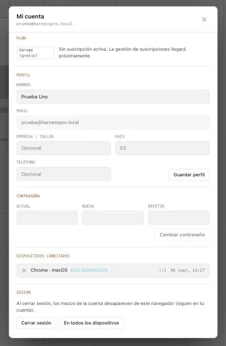
- Plan: Garage (free), Pro or Team. Subscription management is coming soon.
- Profile: name, company/workshop, country and phone. The email cannot be changed here.
- Password: asks for the current one and the new one twice. If you forgot it, for now the administrator resets it.
- Connected devices: every open session with its browser, OS, IP and last activity. Sign out the other sessions keeps only this one.
- Sign out removes the account's harnesses from this browser (they stay in your account). On all devices also closes the other sessions.
ManagementPlans and payments
harnessPRO has three plans. You see and change your plan in My account → Plan; payment happens in Stripe and harnessPRO never sees your card.
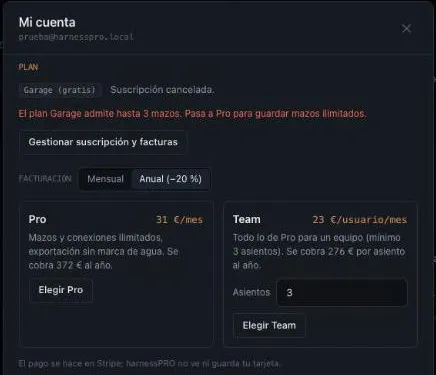
| Plan | Precio | Incluye |
|---|---|---|
| Garage | Free | Up to 3 saved harnesses · up to 50 connections per harness · all views and the full editor · watermarked exports · account and sync included. |
| Pro | €39/month or €372/year (€31/month) | Unlimited harnesses and connections · exports without watermark · Digi-Key catalogue and PDF import · revisions. |
| Team | €29/seat/month or €276/seat/year (€23/month) · minimum 3 seats | Everything in Pro for every seat · one payment for the team · seats adjustable from the portal. |
What happens at the limit
On Garage, trying to create a fourth harness or the 51st connection opens My account with the notice and that change is not saved; what you already have is kept. Moving to Pro removes the limits and the watermark on PDF, Excel and CSV.
Subscribe, change and cancel
In My account → Plan: pick monthly or annual and press Choose Pro or Choose Team (with the number of seats). Stripe charges you and, when you return, your plan is active. With an active subscription, changing plan opens the Stripe portal on your subscription (with proration), and Manage subscription and invoices lets you change the card, cancel at period end and download invoices. Every invoice also appears under Invoices and payments.
If a payment fails
Stripe retries for a few days and emails you. Meanwhile you keep your plan for up to 14 days from the start of the unpaid period; if it is still unpaid, the account goes back to Garage (harnesses are not deleted, but you cannot create more than 3 or add connections beyond 50 until you catch up). Once paid, the plan comes back by itself.
ManagementRevisions
☰ → Revisions…. Named snapshots for marking milestones.
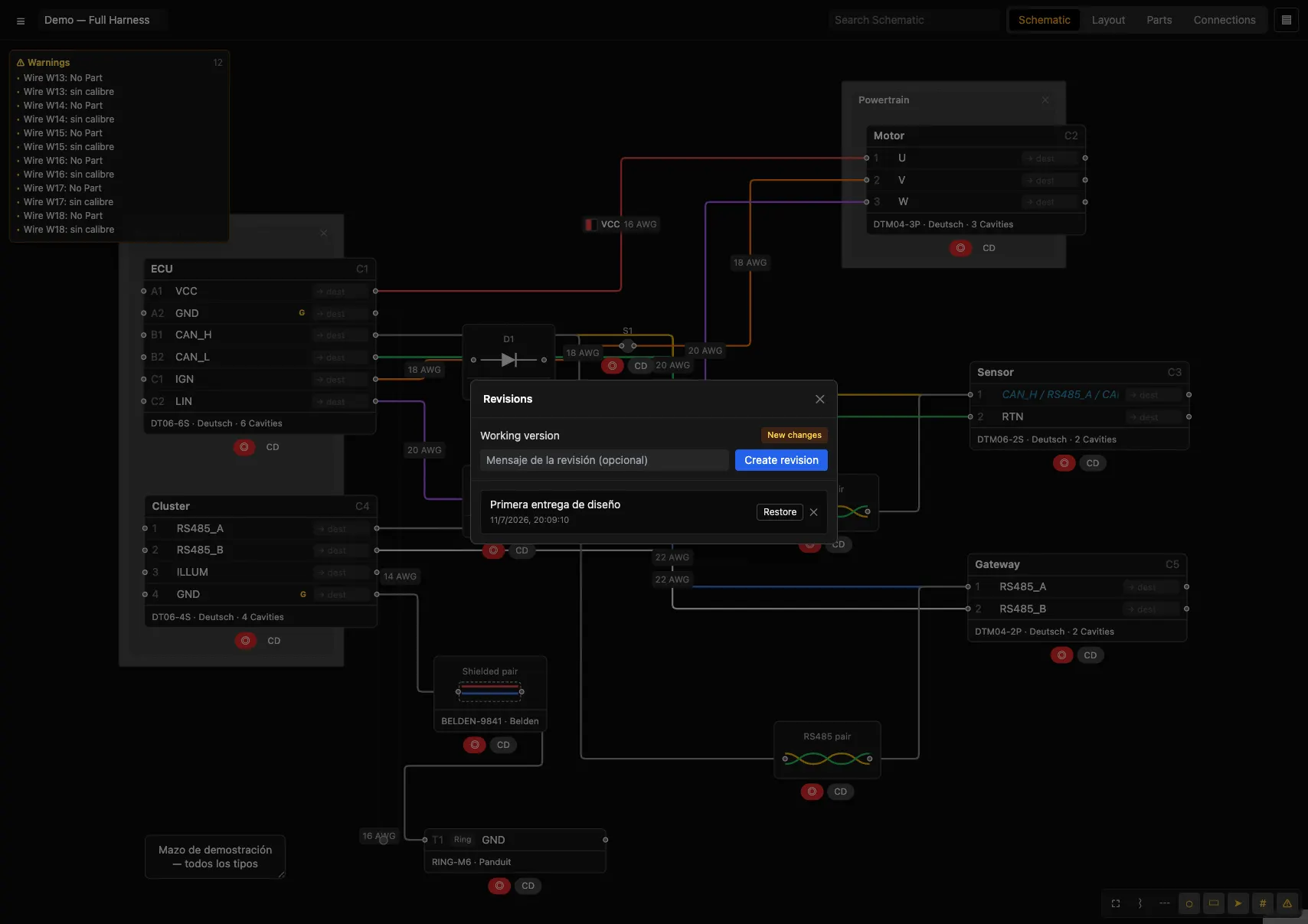
- Working version: shows "New changes" or "No new changes" relative to the last revision.
- Create revision: saves the state with a message.
- Restore: reverts to a revision's state (warns that current work will be overwritten).
- The revision number appears in the PDF title blocks.
ManagementExport
☰ → Export. All manufacturing documentation from a single source.
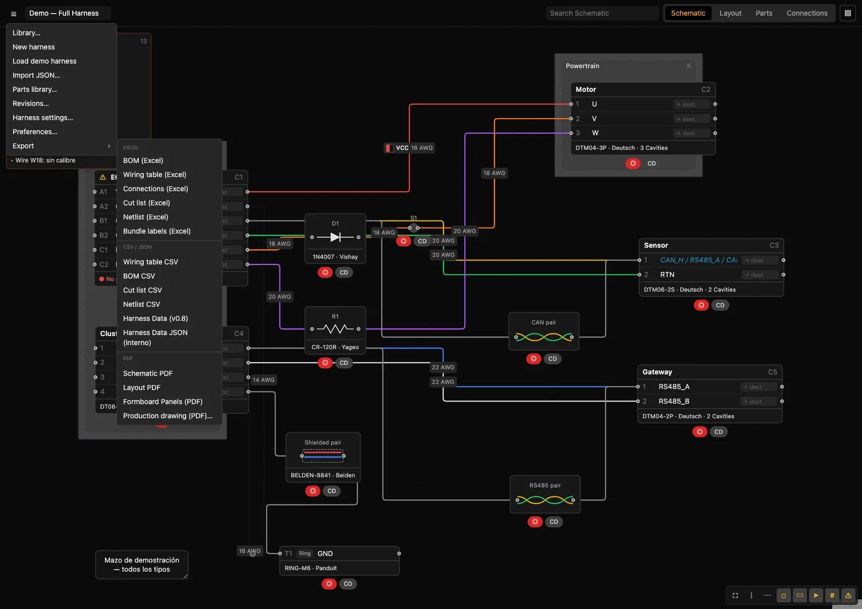
Excel
| Export | Content |
|---|---|
| BOM (Excel) | Bill of materials with Part Number, Manufacturer, Kind, Qty. |
| Wiring table (Excel) | Wires with From/To/Color/Gauge/Length/Covering/Wire Part. |
| Connections (Excel) | Grouped by connector, with pin, signal, destination, color, gauge and part. |
| Cut list (Excel) | Cut length per wire: length + strip. |
| Netlist (Excel) | Nets with signal and nodes. |
| Bundle labels (Excel) | Bundle labels (From/To/Label/Wires/Length). |
CSV / JSON
Wiring table CSV · BOM CSV · Cut list CSV · Netlist CSV · Harness Data (v0.8) (compatible with harness.design) · Harness Data JSON (internal).
- Schematic PDF / Layout PDF — identical to the screen (a real capture of the canvas) with a title block.
- Formboard Panels — the layout at scale with the grid.
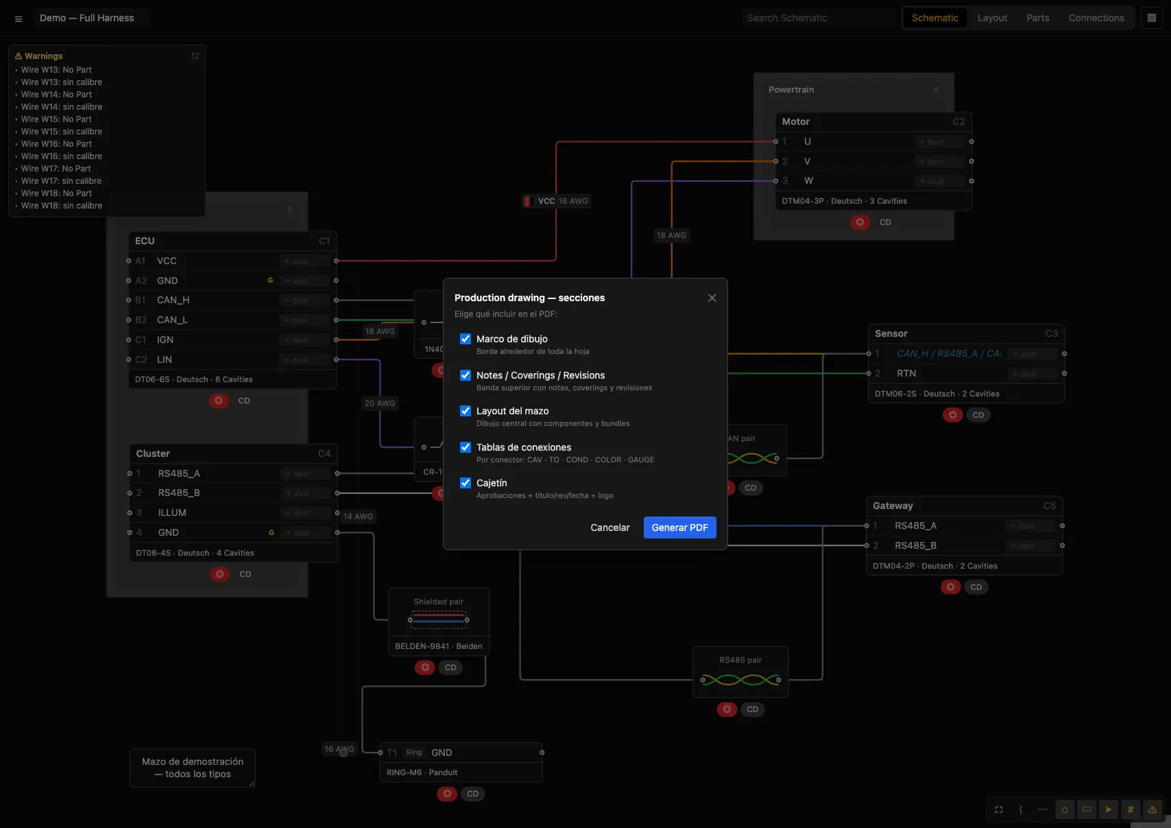
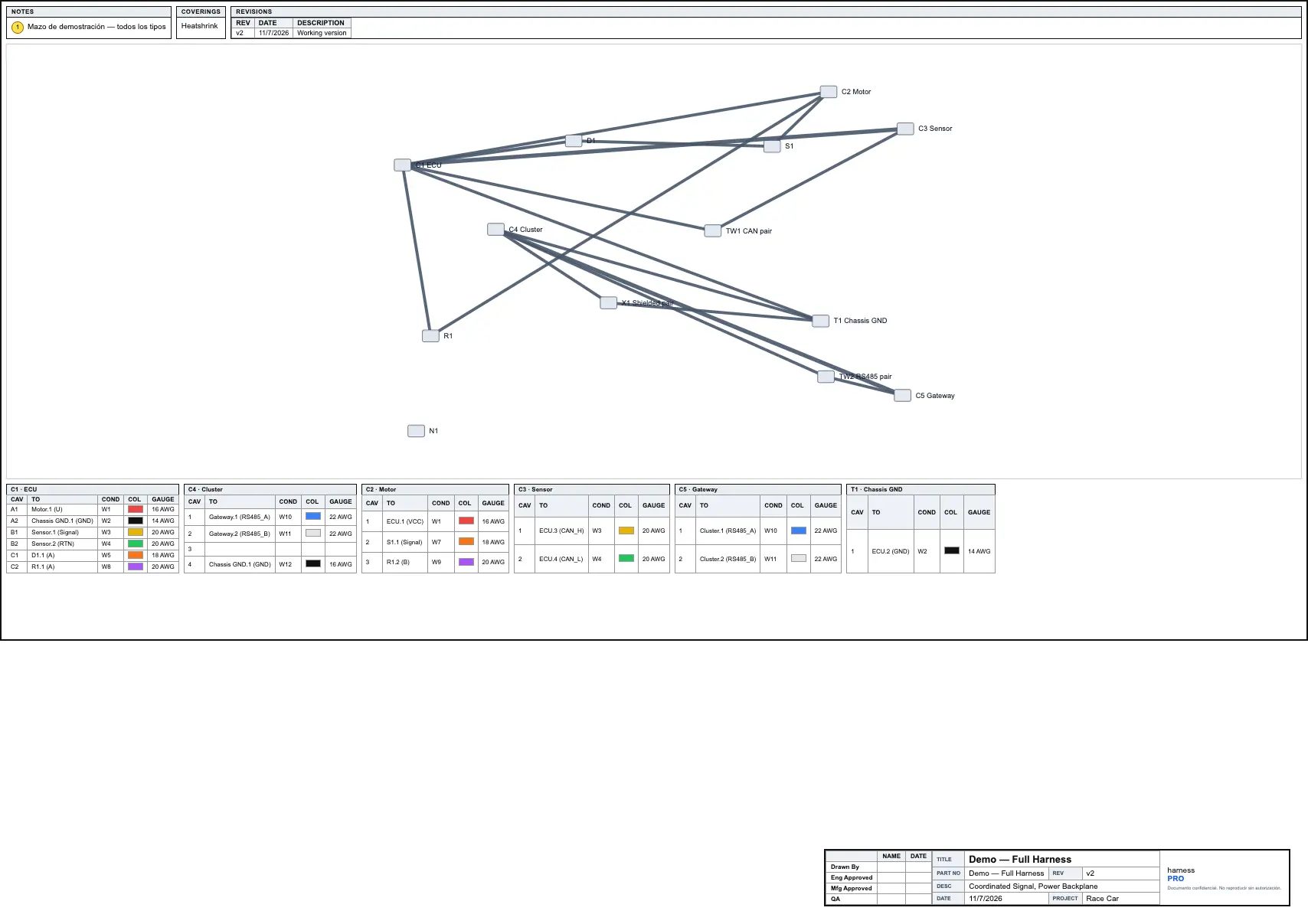
- Production drawing… — the full manufacturing sheet; opens a modal to choose which sections to include: frame, Notes/Coverings/Revisions band, layout, per-connector tables, title block.
ManagementHarness settings
Settings for the current harness (☰ → Harness settings…).
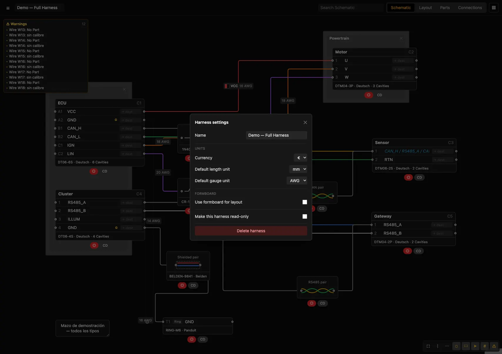
| Setting | Values |
|---|---|
| Name | Harness name. |
| Currency | $ · € · £ · ¥ |
| Default length unit | mm · cm · m · in · ft · yd |
| Default gauge unit | AWG · mm² · cmil · kcmil |
| Formboard | Enable + panel/orientation/scale/bend (see Formboard). |
| Background image | Image under the drawing, one per view (see below). |
| Make read-only | Locks editing of the harness. |
| Delete harness | Deletes the current harness. |
Background image
Place an image under the drawing to work on top of it: the vehicle blueprint, a photo of a real harness or a reference diagram. Schematic and Layout each have their own, with independent settings.
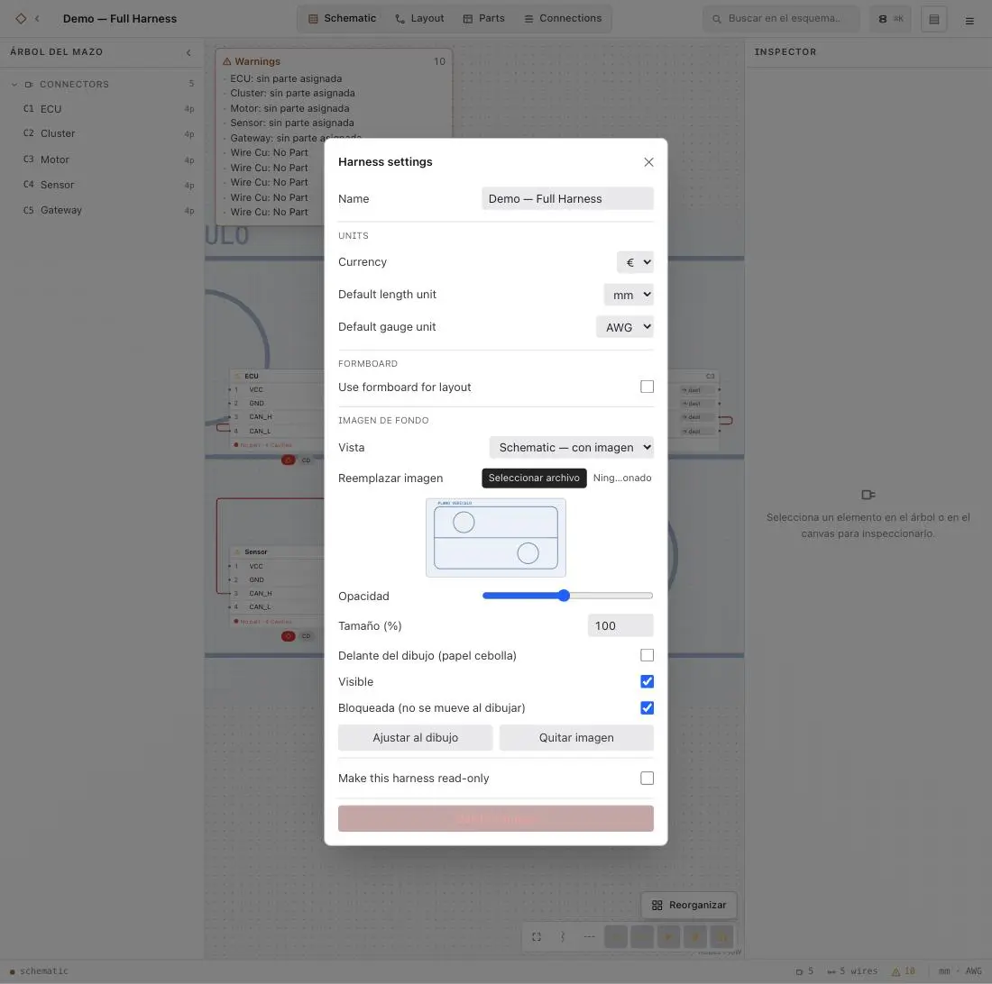
| Control | What it does |
|---|---|
| View | Which of the two views the settings below apply to. Views that already have an image show as «— con imagen». |
| Image | PNG, JPG, WebP or SVG. Bitmaps are resized to 2000 px and compressed on import; SVG is stored as-is and stays sharp at any zoom level. |
| Opacity | 5–100 %. Lower it so the drawing stands out against the background. |
| Size (%) | Scale relative to the original size, keeping the aspect ratio. |
| In front of the drawing | Onion skin: puts the image on top of the schematic. Needed on dense harnesses, where the (opaque) connectors would hide a background image. Combine it with a low opacity. |
| Visible | Hides the image without deleting it. |
| Locked | Locked (the default) ignores the mouse: you draw on top without nudging it. Unlock it to drag the image into place. |
| Fit to drawing | Repositions and enlarges the image until it spans the harness (what happens on import). |
| Remove image | Deletes the image for that view. |
The image is anchored to the canvas: it pans and scales with the zoom, like paper under a tracing. When inserted it is centred on the drawing, faint and locked.
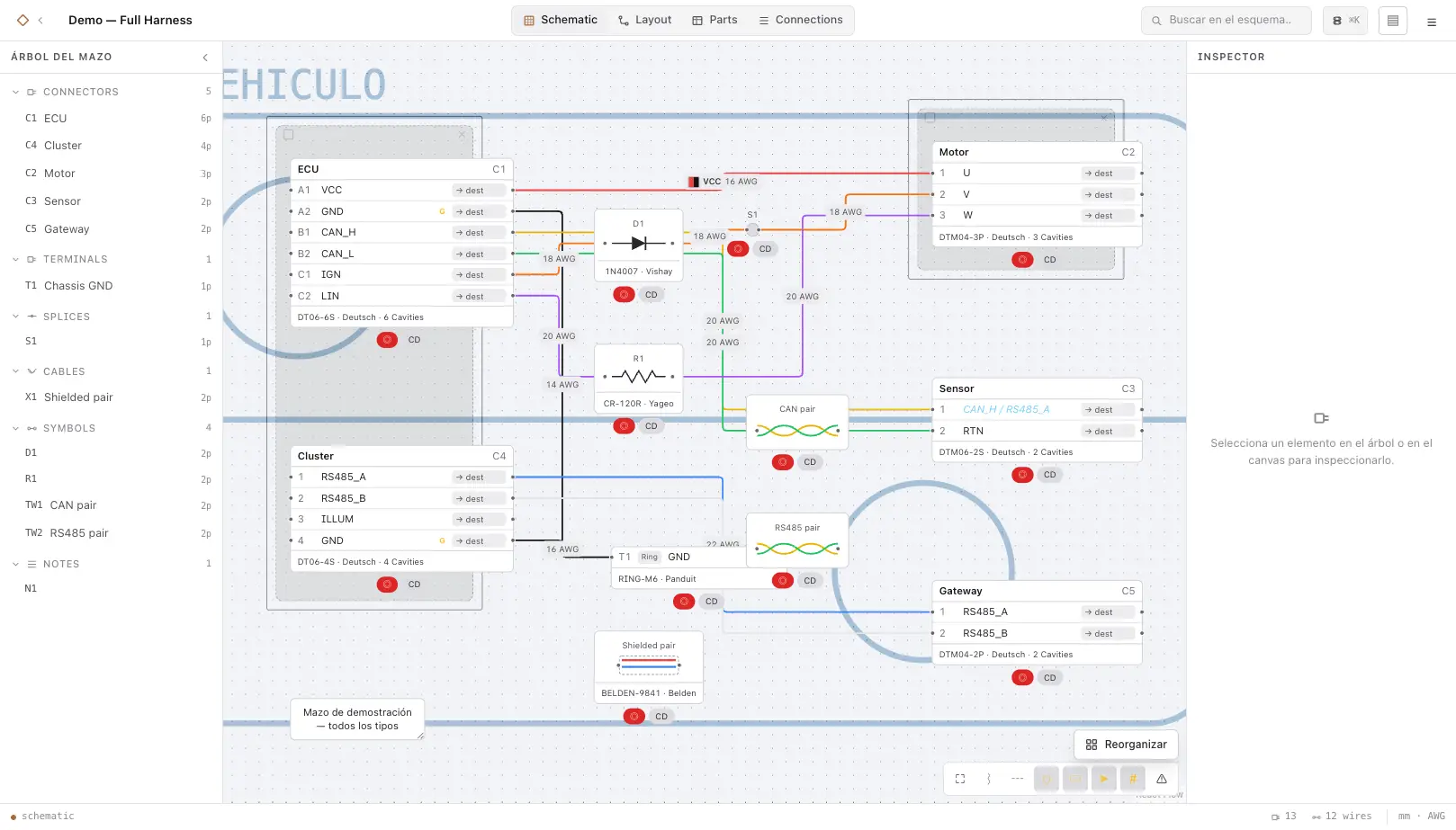
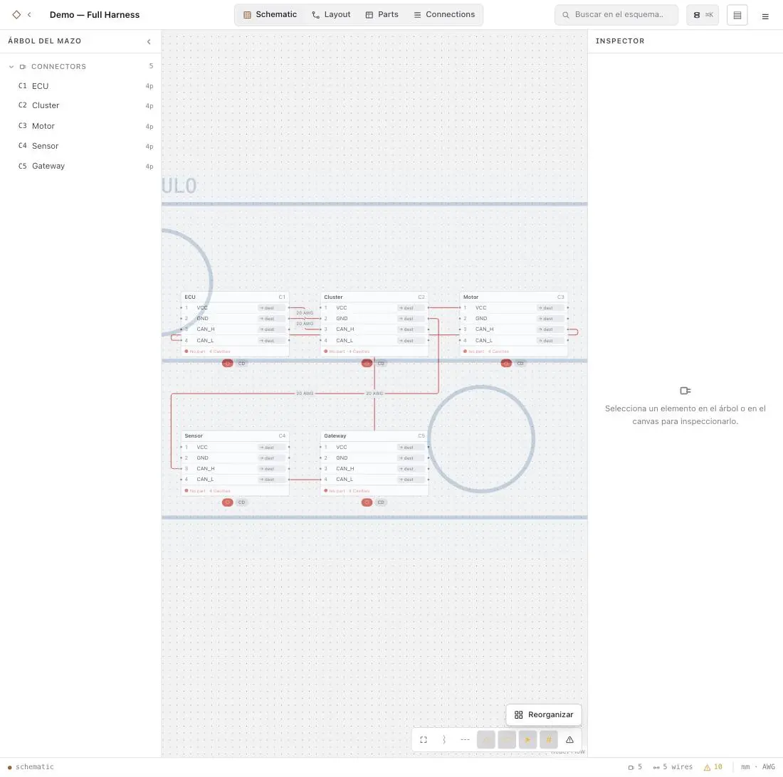
The image travels inside the harness: it is exported with the JSON and stored in every revision. That is why bitmaps are compressed on import; if you need maximum sharpness, use SVG.
ManagementPreferences
Application settings (☰ → Preferences…), applied to all harnesses.
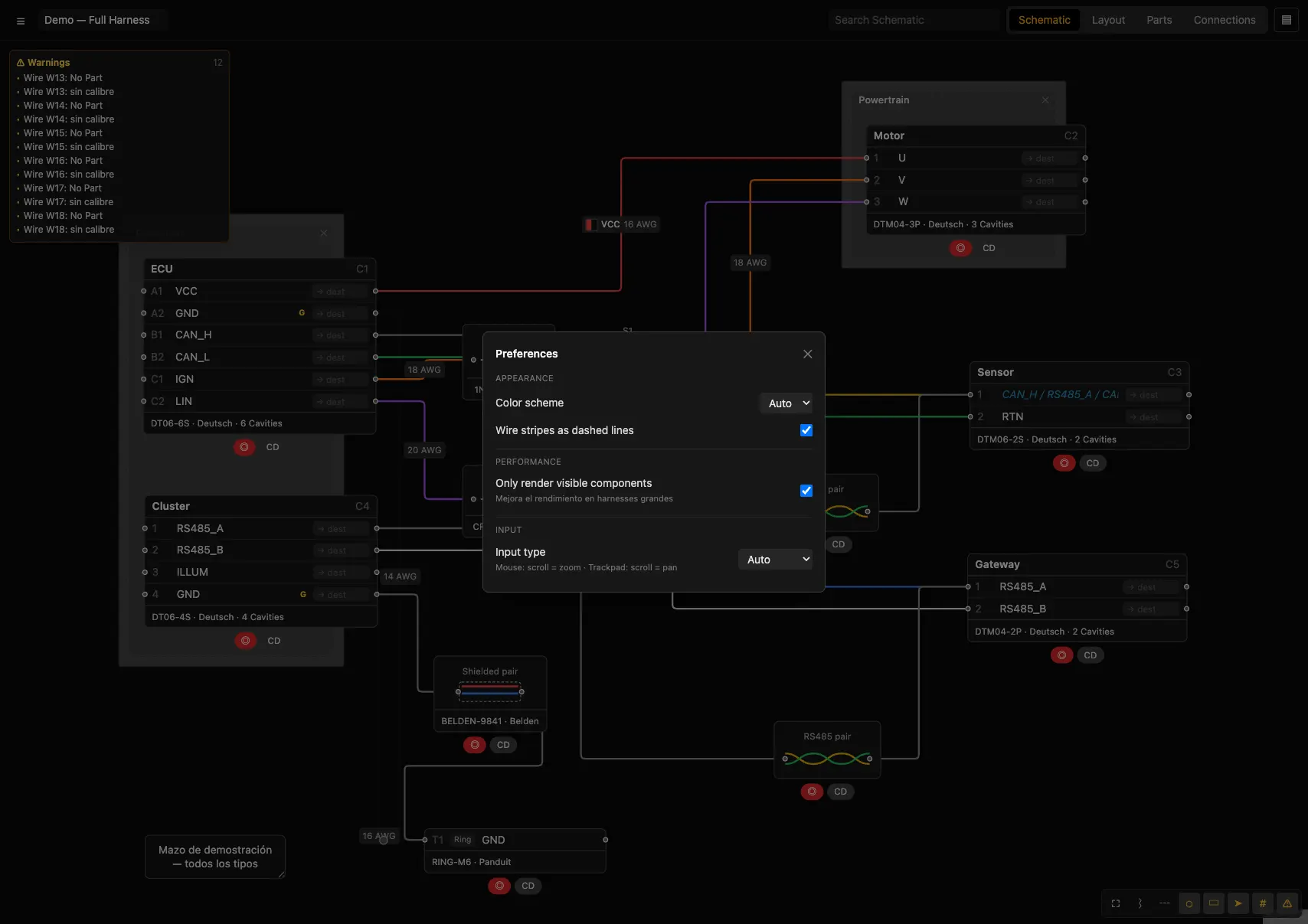
| Preference | Options |
|---|---|
| Color scheme | Dark · Light · Auto |
| Wire stripes as dashed lines | Dashed stripe vs. parallel |
| Only render visible components | Improves performance on large harnesses |
| Input type | Auto · Mouse (scroll=zoom) · Trackpad (scroll=pan) |
ManagementInteroperability (JSON v0.8)
harnessPRO speaks harness.design's JSON v0.8 format.
- Export: Export → Harness Data (v0.8). You can open your harness in harness.design.
- Import: ☰ → Import JSON… with its file; harnessPRO detects the format and converts it (connectors, terminals, splices, diodes, resistors, cables, twisted wires, notes, wires, mates and parts).
ReferenceFull tutorial
Let's build a harness from start to finish: an ECU that powers a motor and reads a sensor.
Create the harness
☰ → New harness. Rename it "Demo Motor" at the top.Add the connectors
Schematic → right-click → Connector (×3). Name them ECU, Motor and Sensor; set their cavities in the selection panel.Designations and signals
On ECU, menu → Designations → Grid (2 columns). Double-click the cavities:VCC,GND(make it global),SIG.Connect
DragECU.VCC→Motor.1. Or enable Destinations (D) and type each cavity's destination + Enter (focus jumps to the next one).Wire properties
Right-click a wire → Color (red), Gauge (18 AWG), Ident "VCC".Parts and BOM
Parts view → Add part ▾ → Connector; fill in the part number and assign it (right-click → Assign Part). Create a wire part and assign it with "Select wires on net".Lay out the harness
Layout view: position the connectors; the trunk routes itself. Right-click on empty space → branch point with a boot wherever it splits; set segment lengths.Validate
Enable Show warnings and resolve down to 0 warnings.Export
☰ → Export → Production drawing… → choose sections → Generate. Also add Cut list and BOM in Excel.
ReferenceKeyboard shortcuts
| Shortcut | Action |
|---|---|
| F | Fit to view. |
| N · U · P · C · D · I · W | Toolbar toggles (see above). |
| Ctrl/Cmd+Z | Undo. |
| Ctrl/Cmd+Shift+Z | Redo. |
| Delete / Backspace | Delete the selection. |
| Drag a wire | Shape it (layout point). |
| Right-click on empty space (Layout) | Add a branch point. |
ReferenceFrequently asked questions
Where are my harnesses saved?
In your harnessPRO account (server), synced to every device you sign in on. Export to JSON for copies or to exchange with other tools.
Does the PDF come out dark?
No: PDFs are always generated with a light background. Schematic and Layout capture the actual canvas, preserving colors and symbols.
Can I open a harness from harness.design?
Yes: ☰ → Import JSON… with its v0.8 file; it is detected and converted.
How do I separate overlapping wires?
Drag the wire itself (creates a layout point) or use "Add layout point" from its menu.
Are there users, teams or the cloud?
Accounts and sync, yes (see Your account). The Team plan is billed per seat; the shared library and team roles are in development.